![]() ![]() ![]() ![]() ![]()
![]() | ![]() | ![]() ![]()  | |  |
|---|
![]() | | Autor: | | Vytvořeno: 31.07.2014 - Změněno: 00.00.0000 |
This article is under construction.
![]()
![]() Will describe how to tune YK31C controller Will describe how to tune YK31C controller
for higher power, higher currents to motor.
![]()
![]() For reference reasons its available at this stage. For reference reasons its available at this stage.
YK31C, inside labeled as YK31FT
Basically YK31C is PWM controller for brushed DC motor with low voltage protection and current feedback limit.
![]()
![]() Core is triangular generator, which is combined with throttle level into PWM modulation. Core is triangular generator, which is combined with throttle level into PWM modulation.
![]()
![]() To be able to control the current flowing through the motor, there is pair of shunts (looking as U bent wire). To be able to control the current flowing through the motor, there is pair of shunts (looking as U bent wire).
![]()
![]() In fact shunt isnt just wire. It has some amount of very small resistance, but together with high current it will generate some voltage on it. In fact shunt isnt just wire. It has some amount of very small resistance, but together with high current it will generate some voltage on it.
![]()
![]() Ohm law says voltage = current * resistance. So the higher resistance or current is, more voltage is gathered. Ohm law says voltage = current * resistance. So the higher resistance or current is, more voltage is gathered.
![]()
![]() This voltage is fed into comparator which compares its value with preset value. If its higher, it will kill the output. This voltage is fed into comparator which compares its value with preset value. If its higher, it will kill the output.
![]()
![]() This way controller adjust the output current. This way controller adjust the output current.
Available versions of YK31C
YK31 - SMD parts
Why to make a mod ?
I didnt plan to mod it first. But I bought 800W quad bike for my kids and wait - It has 10A fuse while it has 36V battery.
![]()
![]() Something is wrong here ! Simply 10A * 36V = 360W, if you try to put more, the fuse will blow. Something is wrong here ! Simply 10A * 36V = 360W, if you try to put more, the fuse will blow.
![]()
![]() So that mean the quad bike isnt 800W at all. Even when labeled so on motor, on controller, in papers. Not really 800W. So that mean the quad bike isnt 800W at all. Even when labeled so on motor, on controller, in papers. Not really 800W.
![]()
![]() That was the time, when I started to search internet for scheme. Maybe I can fix it, right ? Lets get what I paid for ! That was the time, when I started to search internet for scheme. Maybe I can fix it, right ? Lets get what I paid for !
![]()
![]() In fact you can also push more power from any version. Mod 250W to 350W or even 500W or yet more... sounds pretty good, does it ? In fact you can also push more power from any version. Mod 250W to 350W or even 500W or yet more... sounds pretty good, does it ?
Wrong schemes of YK31C from internet:
What I found was lots of garbage. Not much info about YK31C controller out there.
![]()
![]() Schemes are missing parts, has wrong values and wrong labels. Did not help much. Schemes are missing parts, has wrong values and wrong labels. Did not help much.
Correct scheme of YK31C:
How can I modify something, if I do not know what to focus on ?
![]()
![]() So I started reverse engineering and converted pcb into circuit. So I started reverse engineering and converted pcb into circuit.
![]()
![]() Now it makes a sense. Much more clear what is happening there. Now it makes a sense. Much more clear what is happening there.
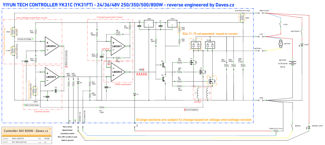
High resolution YK31C wiring (455.3kb)
Circuit description
![]()
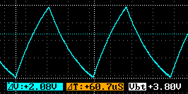
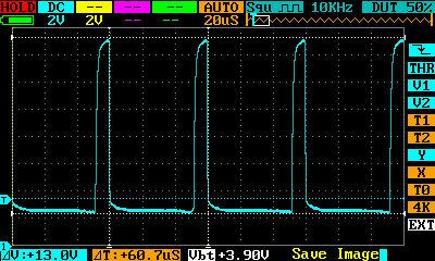
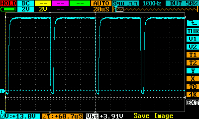
![]() Here goes how the circuit is working. Part about triangle generator, followed by modulator and low voltage protection. Here goes how the circuit is working. Part about triangle generator, followed by modulator and low voltage protection.
![]()
![]() Not so important for modders who do not care about circuit idea. Not so important for modders who do not care about circuit idea.
Triangle output from LM339/1:
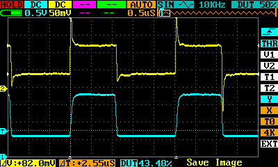
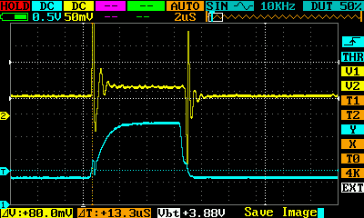
Modulated output (PWM) of LM339/2 (minimal / maximal):
Yellow is input voltage (motor current) on 339/3, blue is pwm output x10.
Ways of YK31C controller tuning
I found at least four ways how to power enhance the controller.
![]()
![]() Some mods are very easy, but hard to fine tune or even guess what it will do :) Some mods are very easy, but hard to fine tune or even guess what it will do :)
MOD #1 - shunt mod
Shunt mod is the easiest one. You need just to solder 1/3 of shunt.
![]()
![]() That will decrease its resistance, so less voltage will be generated. That will decrease its resistance, so less voltage will be generated.
![]()
![]() Remember the ohm law: voltage = current * resistance. Remember the ohm law: voltage = current * resistance.
![]()
![]() We have same current, but less resistance. It means less voltage on output. We have same current, but less resistance. It means less voltage on output.
![]()
![]() So we can allow more current with lower resistance to fit into same voltage. So we can allow more current with lower resistance to fit into same voltage.
![]()
![]() Problem is, its very bad controllable. No fine tune at all. Hard to preset. Problem is, its very bad controllable. No fine tune at all. Hard to preset.
MOD #2 - YK31C shunt bypass
If you cut the wire between R11 and shunt, and replace with 1k trimmer, you can fine tune the output power.
![]()
![]() From OW to maximum. Just be careful - current drivers and also the motor has its limits. Will burn out, when you try to apply too much power. From OW to maximum. Just be careful - current drivers and also the motor has its limits. Will burn out, when you try to apply too much power.
MOD #3 - YK31C current reference bypass
This one is very similar to previous one. Just you did not fake the feedback and instead of you modify directly the reference point.
![]()
![]() Also this will allow to fine tune from 0W to max, so take care. Also this will allow to fine tune from 0W to max, so take care.
MOD #4 - YK31C current reference change
If you plan one time change, you can use table below and replace resistor with new value.
![]()
![]() It will change power output immediately and it will be save. Cant go behind the borders... It will change power output immediately and it will be save. Cant go behind the borders...
![]()
![]() Here goes table. (will be added later) Here goes table. (will be added later)
| - | 250W | 350W | 500W | 800W | | 24V | ? | 190 | ? | ? | | 36V | ? | 120 | 240 | 330 | | 48V | ? | ? | ? | ? | |
Can I use it for 12V motors? / Can I use different voltage?
![]()
![]() Yes. First you need modify the Low voltage protection circuit. This will not work, when you use any version on different voltage. Yes. First you need modify the Low voltage protection circuit. This will not work, when you use any version on different voltage.
![]()
![]() There are two ways. You can correctly set value of R19 R31, or remove R16 R17 R32 R33 permanently. There are two ways. You can correctly set value of R19 R31, or remove R16 R17 R32 R33 permanently.
![]()
![]() Now any version will work on any voltage. You have to set maximum current reference R14 R15 R34 R35. Now any version will work on any voltage. You have to set maximum current reference R14 R15 R34 R35.
![]()
![]() Use tips above or reference table to do so. Use tips above or reference table to do so.
|
|
| ![]() |  | ![]() |  |
![]()  | Copyright 2001-2015
![]() |  |
|---|
![]() | Materiál ze serveru daves.cz nesmí být publikován bez souhlasu autora.
David Spilka (Daves), tel.: 775 328 374, email: pošli email, ICQ: 109318615
|
| ![]() |  | ![]() |  |
![]()
![]()  | Google search
![]() |  |
|---|
![]() | ![]()
Nenašli jste na těchto stránkách co jste hledali ? Zkuste Google...
|
| ![]() |  | ![]() |  |
| ![]() | ![]() ![]()  | Statistika
![]() |  |
|---|
![]() | | Právě prohlíží: | 50 | | Právě přihlášeno: | 0 | | Dnes návštěv: | 146 | | Celkem návštěv: | 33143441 |
| | Článků: | 179 | | Fotografií: | 4127 | | Komentářů: | 1245 | | Uživatelů: | 311 |
![]() |
| ![]() |  | ![]() |  |
![]()
![]() |